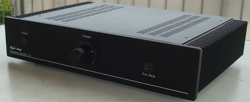
Ultra High-End Transistoramp Sirius V4.5
circuit
 |
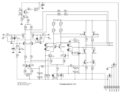
Above you see one chanel of the balanced DC-coupled Class-A ultra high-end amplifier. The input stage is a differential amplifier in cascode topology to reduce the Miller-effect. The 2SA1156 are holding a constant voltage of -24 Volt to the drains of the 2SJ74. The signal current, generated by the 2SJ74 passes the 2SA1156 and generates a voltage drop along the resistors R05x. The voltage gain of this stage can be calclated as the quotient of 6,8k/300 = 22 (the load of the 2SC1815 not taken in account). The second stage consisting of the 2SC1845 and 2SC3676 is also a differential amplifier in cascode topology. Its gain is determined by the quotient of 102K/100, reduced by the Ube voltage drop of the 2SC1845 to 1000. The last stage works as impedance converter in order to decrease the output impedance and has a voltage gain of 1. The open loop gain of this design is about 22000 and the closed loop gain is reduced by four 150K feedback resistors to 1000. The 10p silver micas are working as frequency compensation and prevent the amplifier from generating TIM. The current of the output transistors is determined by the resistors R11x to a value of 15mA. The constant current sources T03x draws 0,5mA from the 1,5mA, supplied by the T02x. R56 is used to compensate offset voltages. The cascading of the two current sources T51 and T52 in the first stage results in a much higher output impedance to some gigaohm. The same topology is used in the output stage. The current sources T07x and T08x provide a very high output impedance which leads to a high degree of decoupling noices from the power supply.
It is recommended to use the regulated power supply. The transformer needs secondary 2x330V/150mA and 2x15V/100mA.
starting up
WARNING!!!
Remember that you are handling with high voltages that can be dangerous to life. So if you are working on powerd on devices use only one hand in order to prevent electrical shock.
After connecting the amplifier to the power supply you can begin with adjustment. Connect the input to ground and adjust the output between +Out and -Out to 0V with R56. Now connect your voltmeter to +Out and ground and use R50 to adjust it to 0V. Now repeat these two steps again. Repeat this procedure after 20 minutes when the amplifier is warmed up.The amplifier is now adjusted and ready for use.
Result
With a supply voltage of +/-400 Volt the amplifier can output more then 500 Volt eff (=1500Volt Vss from stator to stator). The power consumption of the amplifier is 80 Watt. Problems with offset drift when using the 2SJ74 instead of the dual jfet 2SJ109 did not occure. A change of the environmental temperature of 20° C resulted in an voltage drift of 1 Volt at the output, and that is nothing for an electrostatic headphone.
It can drive all STAX Pro headphones (580Volt BIAS), if you reduce BIAS to 280Volt it can drive all STAX headphones. Certainly you can drive other electrostatic headphones like KOSS, Sennheiser, etc too, just fit the BIAS to the desired value. The amplifier sounds very clear and detailed. The basses are dry and strong, the frequencies at the high end are sounding very transparent. The very fine resolution of this amplifier has reached a level that will easily outclass most other amplifier out there.
Download the complete set (layout, schematics, partlist, etc.) here.
Measurement results (supply voltage +/-400Volt, all voltages RMS)
distortion level vs. output voltage, f=1KHz:
100Volt: 0,007%
300Volt: 0.03%
400Volt: 0,09%
450Volt: 0,18%
500Volt: 1%
distortion level vs. frequency:
Uout = 100Volt:
100Hz: 0,013
1KHz: 0,007%
10KHz: 0,012%
Uout = 300Volt:
100Hz: 0,03%
1KHz: 0,03%
10KHz: 0,06%
chanel seperation vs. frequency (Uout = 100Volt):
100Hz: 70dB
1KHz: 55dB
10KHz: 38dB
signal-to-noise ratio: 100dB
output impedance at 1KHz: 300 Ohm
frequency response (-3dB): 0 - 50000 Hz